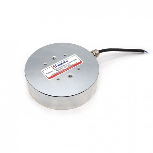
Ø140xØ80x40 Side Gear 24V 33.4W Electromagnet - For Positioning in Packaging Lines and Conveyor Stop - 60% Duty Cycle
$212.50
With installments starting from $14.76!
- Stock: In Stock
- Model: MGK-E-50
- Category: Yuvarlak Elektromıknatıslar
| Stock | : | In Stock |
| Model | : | MGK-E-50 |
| Category | : | Yuvarlak Elektromıknatıslar |
| Quantity | Pack Price | Unit Price | |
|---|---|---|---|
Please contact us for larger quantities.
Product Added to Cart
Ø140xØ80x40 Side Gear 24V 33.4W Electromagnet - For Positioning in Packaging Lines and Conveyor Stop - 60% Duty Cycle
If you have questions about the product, you can contact our team before purchasing.
Product Added to Wishlist
Ø140xØ80x40 Side Gear 24V 33.4W Electromagnet - For Positioning in Packaging Lines and Conveyor Stop - 60% Duty Cycle
The product has been saved to your list so you can access it later. You can turn the product into an order at any time by going to the favorites area. Have fun shopping.
3 days in delivery!
Delivery by 15 September 2026 Tuesday at the latest.
WhatsApp Support
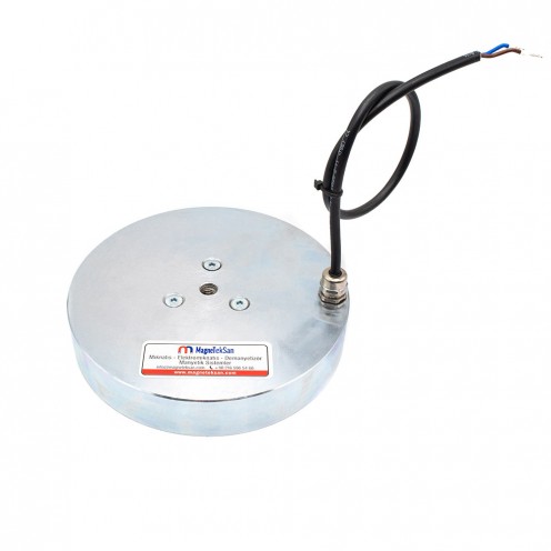
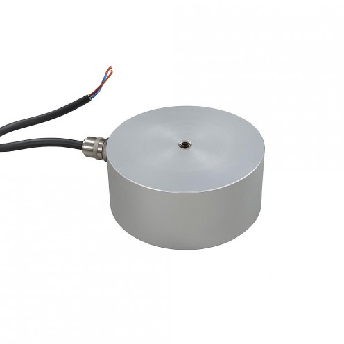
Ø140ר80×40 mm 24V 33.4W Center-Recess Electromagnet
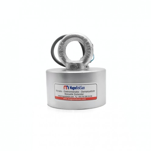
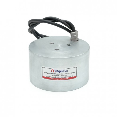
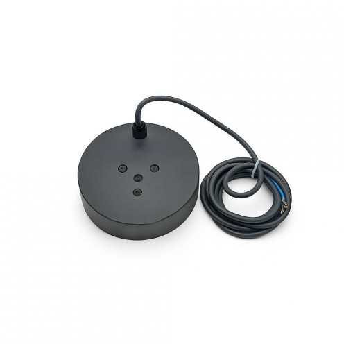
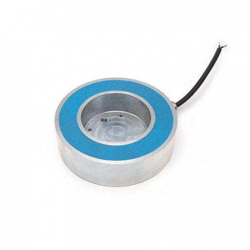
This custom electromagnet features a center recess that self-centers circular parts. It operates at 24V DC and 33.4 W, with a side cable outlet secured by a cable gland. Resin potting provides a sealed structure and the zinc-coated housing ensures durability against dust, vibration and humidity. Designed for intermittent yet intensive use with a 60% duty cycle.
Application Areas
- Robotic pick-and-place for caps, discs and washer-type parts
- Positioning and stopping on packaging/labeling lines
- Centering and temporary clamping on CNC fixtures
- Conveyor stop points and hopper/feeder mouths
- Sample holding in test and measurement setups
Key Features
- Size: Ø140 × Ø80 × 40 mm (outer diameter × center recess diameter × height)
- Supply: 24V DC • Power: 33.4 W • Nominal current: ~1.4 A
- Side cable entry with gland
- Resin-potted sealed body, zinc-coated housing
- 60% duty cycle (intermittent operation)
Technical Notes
- Use a regulated 24V DC power supply. Add a flyback diode across the coil when switching.
- Holding performance depends on surface condition, material thickness, air gap and mounting orientation.
- For 60% duty cycle, a practical guideline is ~3 units on followed by ~2 units off. Provide thermal management for long, heavy-duty use.
Working Principle of Electromagnets
An electromagnet is an industrial component that generates a holding force by creating a magnetic field around an iron core through the electric current passing through its coil. The table below summarizes the general principles.
Electromagnet working logic, components, duty cycle and applications
| Topic | Description |
|---|---|
| Basic Principle | When a DC voltage (e.g. 12V or 24V) is applied, the current flowing through the coil creates a magnetic field around the core and attracts metal surfaces. |
| Main Components | Coil (winding), iron core, housing, connection cables, and where needed a resin coating (heat dissipation/insulation). |
| Strength of the Magnetic Field | Current (A), voltage (V), number of windings, core material, and the cleanliness/tolerance of the contact surface determine the holding force. |
| Duty Cycle | 50% duty: Operates for a set period and then rests (for heat management). 100% duty: Suitable for continuous operation; typically a heat-resistant/resin-coated design. |
| Polarity (Poles) | When the current direction changes, the N–S poles reverse. This is an advantage in direction-controlled applications. |
| Behavior on Power Loss | Standard electromagnet: Holding force is lost when power is cut. Permanent-magnet type: Holding continues when power is cut and releases when power is applied (fail-safe). |
| Heating and Cooling | Heating occurs due to coil resistance. The correct duty cycle, adequate cooling, and a suitable mounting surface are critical for lifespan/performance. |
| Applications | Industrial lifting/holding, automation and robotic grippers, door locks, brake/release mechanisms, CNC and assembly lines. |
| Advantages | Controllable magnetic force, fast response, remote actuation, depending on the application either fail-safe release or fail-safe hold. |
Round Electromagnets Catalog
You can find the technical drawing and standard catalog dimensions of the product in the table below. Please contact us for custom size production.

|
MODEL (BYR5CK/ BUR5CK) |
Dimensions (mm) |
Power WATT |
Voltage VDC |
Duty Cycle % |
Connection POSITION |
Cable Gland PG7-9 |
Min. Plate Thick. (mm) |
Pull Force (N) |
||
|---|---|---|---|---|---|---|---|---|---|---|
| ØD | H | M | ||||||||
| Ø40x30 mm | 40 | 30 | M6 | 5.2 | 24 | 50 | TOP/SIDE | PG7 | 5 | 470 |
| Ø50x30 mm | 50 | 30 | M6 | 7 | 24 | 50 | TOP/SIDE | PG7 | 5 | 760 |
| Ø63x35 mm | 63 | 35 | M6 | 10 | 24 | 50 | TOP/SIDE | PG7 | 8 | 1000 |
| Ø80x40 mm | 80 | 40 | M8 | 15 | 24 | 50 | TOP/SIDE | PG7 | 10 | 2400 |
| Ø100x45 mm | 100 | 45 | M8 | 25 | 24 | 50 | TOP/SIDE | PG7 | 15 | 3400 |
| Ø150x55 mm | 150 | 55 | M16 | 37.2 | 48 | 50 | TOP/SIDE | PG7 | 25 | 9300 |
| Ø180x65 mm | 180 | 60 | M20 | 50 | 48 | 50 | TOP/SIDE | PG7 | 30 | 15000 |
| Ø200x60 mm | 200 | 60 | 3xM12 | 65 | 48 | 50 | TOP/SIDE | PG9 | 35 | 25000 |
| Ø250x80 mm | 250 | 80 | 3xM12 | 90 | 48 | 50 | TOP/SIDE | PG9 | 40 | 30000 |
| Ø280x110 mm | 280 | 110 | 3xM12 | 150 | 48 | 50 | TOP/SIDE | PG9 | 50 | 40000 |
| Ø300x130 mm | 300 | 130 | 3xM12 | 180 | 48 | 50 | TOP/SIDE | PG9 | 80 | 45000 |
| Dimensions | |
| Diameter | 126-150 mm |
| Height | 40 mm |
| Magnet Properties | |
| Coating | Zinc (Zn) |
| Color2 | Gray |
| Gaussian Value | 7000-8000 Gaussian |
| Magnet Attraction Distance | 0-5 cm |
| Shape | Round |
| Strenght | 50-75 kg |
| Tolerance | ± 1 mm |
| Max. Operating Temperature | 100°C |
| Magnet Type | Electric |
| Material Properties | |
| Complete Stainless2 | Yes |
| External Material Feature2 | Steel |
| Exterior Material Quality | 304 Quality Stainless |
| Sealing | Yes |