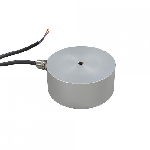
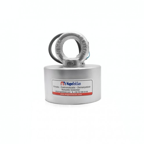
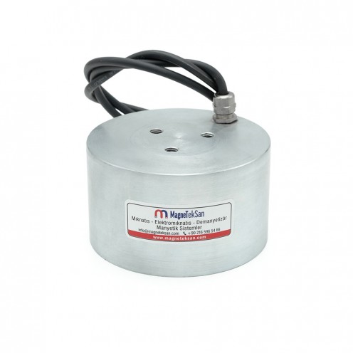
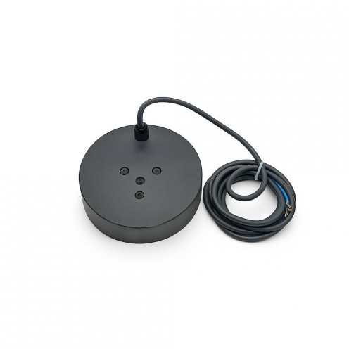
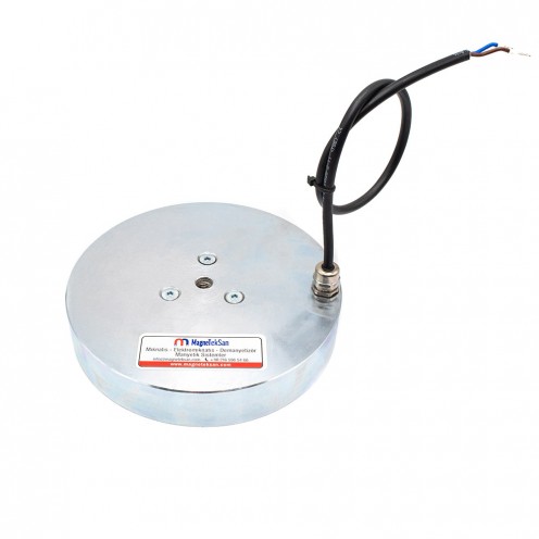
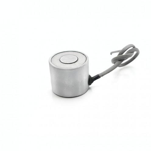
Ø40x30 mm 24V Electromagnet - Side Gear Female Connection, 50% Duty Cycle, High Magnetic Force, Compact Design For Industrial Use
With installments starting from $6.77!
- Stock: In Stock
- Model: MGK-E-33
- Category: Yuvarlak Elektromıknatıslar
| Stock | : | In Stock |
| Model | : | MGK-E-33 |
| Category | : | Yuvarlak Elektromıknatıslar |
| Quantity | Pack Price | Unit Price | |
|---|---|---|---|
| 2 Quantity | $175.50 | $87.75 | |
| 3 Quantity | $248.63 | $82.88 | |
Please contact us for larger quantities.
Ø40x30 mm 24V Electromagnet - Side Gear Female Connection, 50% Duty Cycle, High Magnetic Force, Compact Design For Industrial Use
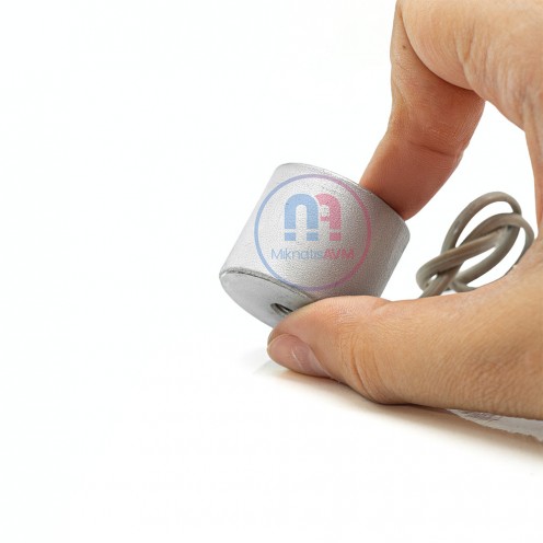
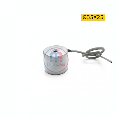
The Ø40×30 mm 24V DC electromagnet with side gland female thread connection is designed for short-term, high-power magnetic applications.
With a 50% duty cycle, it delivers strong holding force and quick response, ideal for repetitive magnetic operations.
Constructed with a 304 stainless steel body and zinc protective coating, it ensures long service life and excellent corrosion resistance.
Its 7000–8000 Gauss magnetic strength and side exit connection make it an efficient solution for automation lines, robotic systems, and industrial locking mechanisms.
Applications
-
Industrial automation and conveyor systems
-
Electromechanical locking systems
-
Robotic gripping and release applications
-
CNC and assembly lines
-
Metal separation and transport mechanisms
Working Principle of Electromagnets
| Topic | Description |
|---|---|
| Basic Principle | When a DC voltage (e.g. 12V or 24V) is applied, the current flowing through the coil creates a magnetic field around the core and attracts metal surfaces. |
| Main Components | Coil (winding), iron core, housing, connection cables, and where needed a resin coating (heat dissipation/insulation). |
| Strength of the Magnetic Field | Current (A), voltage (V), number of windings, core material, and the cleanliness/tolerance of the contact surface determine the holding force. |
| Duty Cycle | 50% duty: Operates for a set period and then rests (for heat management). 100% duty: Suitable for continuous operation; typically a heat-resistant/resin-coated design. |
| Polarity (Poles) | When the current direction changes, the N–S poles reverse. This is an advantage in direction-controlled applications. |
| Behavior on Power Loss | Standard electromagnet: Holding force is lost when power is cut. Permanent-magnet type: Holding continues when power is cut and releases when power is applied (fail-safe). |
| Heating and Cooling | Heating occurs due to coil resistance. The correct duty cycle, adequate cooling, and a suitable mounting surface are critical for lifespan/performance. |
| Applications | Industrial lifting/holding, automation and robotic grippers, door locks, brake/release mechanisms, CNC and assembly lines. |
| Advantages | Controllable magnetic force, fast response, remote actuation, depending on the application either fail-safe release or fail-safe hold. |
Round Electromagnets Catalog

|
MODEL (BYR5CK/ BUR5CK) |
Dimensions (mm) |
Power WATT |
Voltage VDC |
Duty Cycle % |
Connection POSITION |
Cable Gland PG7-9 |
Min. Plate Thick. (mm) |
Pull Force (N) |
||
|---|---|---|---|---|---|---|---|---|---|---|
| ØD | H | M | ||||||||
| Ø40x30 mm | 40 | 30 | M6 | 5.2 | 24 | 50 | TOP/SIDE | PG7 | 5 | 470 |
| Ø50x30 mm | 50 | 30 | M6 | 7 | 24 | 50 | TOP/SIDE | PG7 | 5 | 760 |
| Ø63x35 mm | 63 | 35 | M6 | 10 | 24 | 50 | TOP/SIDE | PG7 | 8 | 1000 |
| Ø80x40 mm | 80 | 40 | M8 | 15 | 24 | 50 | TOP/SIDE | PG7 | 10 | 2400 |
| Ø100x45 mm | 100 | 45 | M8 | 25 | 24 | 50 | TOP/SIDE | PG7 | 15 | 3400 |
| Ø150x55 mm | 150 | 55 | M16 | 37.2 | 48 | 50 | TOP/SIDE | PG7 | 25 | 9300 |
| Ø180x65 mm | 180 | 60 | M20 | 50 | 48 | 50 | TOP/SIDE | PG7 | 30 | 15000 |
| Ø200x60 mm | 200 | 60 | 3xM12 | 65 | 48 | 50 | TOP/SIDE | PG9 | 35 | 25000 |
| Ø250x80 mm | 250 | 80 | 3xM12 | 90 | 48 | 50 | TOP/SIDE | PG9 | 40 | 30000 |
| Ø280x110 mm | 280 | 110 | 3xM12 | 150 | 48 | 50 | TOP/SIDE | PG9 | 50 | 40000 |
| Ø300x130 mm | 300 | 130 | 3xM12 | 180 | 48 | 50 | TOP/SIDE | PG9 | 80 | 45000 |
| Dimensions | |
| Diameter | 40 mm |
| Height | 30 mm |
| Magnet Properties | |
| Coating | Zinc (Zn) |
| Color2 | Gray |
| Gaussian Value | 7000-8000 Gaussian |
| Magnet Attraction Distance | 0-5 cm |
| Shape | Round |
| Tolerance | ± 0,1 mm |
| Max. Operating Temperature | 100°C |
| Magnet Type | Electric |
| Material Properties | |
| Complete Stainless2 | Yes |
| External Material Feature2 | Steel |
| Exterior Material Quality | 304 Quality Stainless |
| Sealing | Yes |