Menu
Your Cart

Ø40x40 mm Electromagnet – 24V, 100% Duty Cycle, High Holding Force, for Industrial and Test Systems

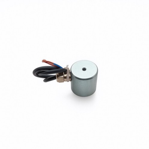
Ø40x40 mm Electromagnet – 24V, 100% Duty Cycle, High Holding Force, for Industrial and Test Systems
$95.00

With installments starting from $6.60!

Stock : In Stock
Model : MGK-E-129
Category : Yuvarlak Elektromıknatıslar
Quantity Pack Price Unit Price
2 Quantity $171.00 $85.50
3 Quantity $242.25 $80.75
5 Quantity $380.00 $76.00
10 Quantity $741.00 $74.10

Please contact us for larger quantities.

Add to Cart
3 days in delivery!
Delivery by 15 September 2026 Tuesday at the latest.
WhatsApp Support
Product Description

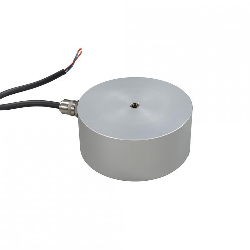
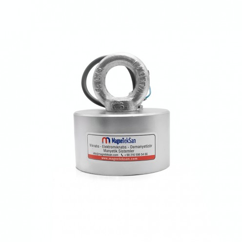
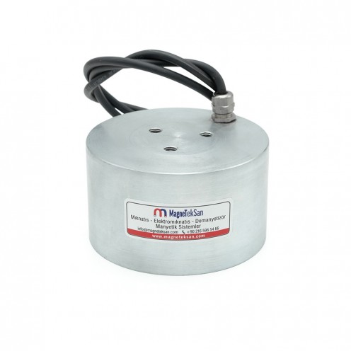
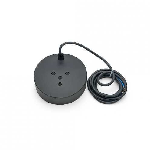
Measuring Ø40×40 mm, this 24V DC electromagnet offers a compact, sturdy, and easy-to-install design with an M6 threaded connection and side cable entry.

Thanks to its 100% duty cycle (continuous operation duty), it operates uninterruptedly during long-term use without overheating or performance loss.

With its strong magnetic field, high holding capacity, and stainless steel body, it is safely used in automation lines, conveyor systems, electromechanical lock mechanisms, and robotic applications.

Its industrial-grade sealed structure, high temperature resistance, and low power consumption ensure efficient operation.


Advantages

  • 100% duty cycle makes it suitable for continuous use
  • High magnetic force and long-life coil design
  • Secure mounting with M6 threaded connection
  • Side cable entry allows for easy routing and protection
  • Stainless steel body, zinc plating, and heat-resistant structure
  • Low power consumption, quiet and vibration-free operation

Working Principle of Electromagnets

An electromagnet is an industrial component that generates a holding force by creating a magnetic field around an iron core through the electric current passing through its coil. The table below summarizes the general principles.

Electromagnet working logic, components, duty cycle and applications

Topic Description
Basic Principle When a DC voltage (e.g. 12V or 24V) is applied, the current flowing through the coil creates a magnetic field around the core and attracts metal surfaces.
Main Components Coil (winding), iron core, housing, connection cables, and where needed a resin coating (heat dissipation/insulation).
Strength of the Magnetic Field Current (A), voltage (V), number of windings, core material, and the cleanliness/tolerance of the contact surface determine the holding force.
Duty Cycle 50% duty: Operates for a set period and then rests (for heat management).
100% duty: Suitable for continuous operation; typically a heat-resistant/resin-coated design.
Polarity (Poles) When the current direction changes, the N–S poles reverse. This is an advantage in direction-controlled applications.
Behavior on Power Loss Standard electromagnet: Holding force is lost when power is cut.
Permanent-magnet type: Holding continues when power is cut and releases when power is applied (fail-safe).
Heating and Cooling Heating occurs due to coil resistance. The correct duty cycle, adequate cooling, and a suitable mounting surface are critical for lifespan/performance.
Applications Industrial lifting/holding, automation and robotic grippers, door locks, brake/release mechanisms, CNC and assembly lines.
Advantages Controllable magnetic force, fast response, remote actuation, depending on the application either fail-safe release or fail-safe hold.

Round Electromagnets Catalog

You can find the technical drawing and standard catalog dimensions of the product in the table below. Please contact us for custom size production.

Round Electromagnet
MODEL
(BYR5CK/
BUR5CK)
Dimensions (mm) Power
WATT
Voltage
VDC
Duty
Cycle %
Connection
POSITION
Cable Gland
PG7-9
Min. Plate
Thick. (mm)
Pull Force
(N)
ØD H M
Ø40x30 mm 40 30 M6 5.2 24 50 TOP/SIDE PG7 5 470
Ø50x30 mm 50 30 M6 7 24 50 TOP/SIDE PG7 5 760
Ø63x35 mm 63 35 M6 10 24 50 TOP/SIDE PG7 8 1000
Ø80x40 mm 80 40 M8 15 24 50 TOP/SIDE PG7 10 2400
Ø100x45 mm 100 45 M8 25 24 50 TOP/SIDE PG7 15 3400
Ø150x55 mm 150 55 M16 37.2 48 50 TOP/SIDE PG7 25 9300
Ø180x65 mm 180 60 M20 50 48 50 TOP/SIDE PG7 30 15000
Ø200x60 mm 200 60 3xM12 65 48 50 TOP/SIDE PG9 35 25000
Ø250x80 mm 250 80 3xM12 90 48 50 TOP/SIDE PG9 40 30000
Ø280x110 mm 280 110 3xM12 150 48 50 TOP/SIDE PG9 50 40000
Ø300x130 mm 300 130 3xM12 180 48 50 TOP/SIDE PG9 80 45000

Applications

  • Continuous-duty automation lines
  • Metal handling and positioning in conveyor systems
  • Electromechanical locking systems
  • Robotic gripper and release mechanisms
  • CNC machines, assembly, and packaging lines
  • Magnetic separator and metal detector systems

Write a review

Dimensions
Diameter 40 mm
Height 40 mm
Magnet Properties
Coating Zinc (Zn)
Color2 Gray
Gaussian Value 7000-8000 Gaussian
Magnet Attraction Distance 0-5 cm
Shape Cylinder
Tolerance ± 1 mm
Max. Operating Temperature 50
Magnet Type Electric
Material Properties
External Material Feature2 Steel