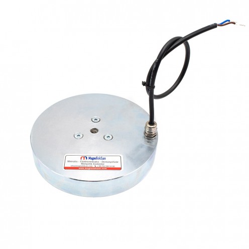
Ø70x35 mm Electromagnet - 60 kg Pull Force
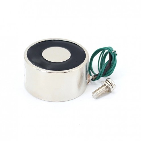

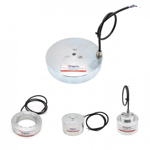


Ø70x35 mm Electromagnet - 60 kg Pull Force
$0.00
With installments starting from $0.00!
| Stock | : | Sadece Teklif |
| Model | : | MGK-E-7035 |
| Category | : | Yuvarlak Elektromıknatıslar |
| Quantity | Pack Price | Unit Price | |
|---|---|---|---|
Please contact us for larger quantities.
Ø70x35 mm Lifting Magnet Features
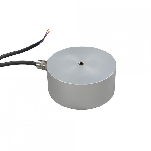
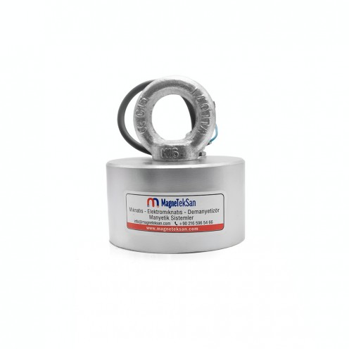
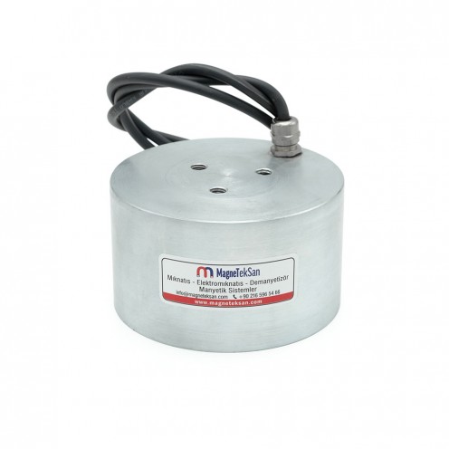
These electromagnets, Ø70x35 mm, P70/35 (70 mm diameter, 35 mm height), are frequently preferred in services such as lid handling, pipe handling and box handling.
In our company in Istanbul, special studies are carried out to provide quality electromagnet products to all our customers. Electromagnets are materials used at almost every point in our daily lives. These magnets are known as electrical products that are energized depending on the existing magnet property. Electromagnets can operate at different levels depending on voltage and current levels. Our electromagnet productions, which are specially prepared in line with the demands of our customers, are designed to be used for various purposes and lead the way in the transportation sector.
Electromagnets are also used in test devices and are an important product for processes such as sheet metal handling, lid handling, box and pipe handling. Electromagnets produced by our company exert a great attraction force despite their small size. They vary according to their waterproof properties and different voltage levels. Our company, which has a wide range of electromagnets, offers long-lasting and successful products. The products, which attract attention with their various operating temperature advantages, have become an indispensable part especially in the automation sector.
Working Principle of Electromagnets
An electromagnet is an industrial component that generates a holding force by creating a magnetic field around an iron core through the electric current passing through its coil. The table below summarizes the general principles.
Electromagnet working logic, components, duty cycle and applications
| Topic | Description |
|---|---|
| Basic Principle | When a DC voltage (e.g. 12V or 24V) is applied, the current flowing through the coil creates a magnetic field around the core and attracts metal surfaces. |
| Main Components | Coil (winding), iron core, housing, connection cables, and where needed a resin coating (heat dissipation/insulation). |
| Strength of the Magnetic Field | Current (A), voltage (V), number of windings, core material, and the cleanliness/tolerance of the contact surface determine the holding force. |
| Duty Cycle | 50% duty: Operates for a set period and then rests (for heat management). 100% duty: Suitable for continuous operation; typically a heat-resistant/resin-coated design. |
| Polarity (Poles) | When the current direction changes, the N–S poles reverse. This is an advantage in direction-controlled applications. |
| Behavior on Power Loss | Standard electromagnet: Holding force is lost when power is cut. Permanent-magnet type: Holding continues when power is cut and releases when power is applied (fail-safe). |
| Heating and Cooling | Heating occurs due to coil resistance. The correct duty cycle, adequate cooling, and a suitable mounting surface are critical for lifespan/performance. |
| Applications | Industrial lifting/holding, automation and robotic grippers, door locks, brake/release mechanisms, CNC and assembly lines. |
| Advantages | Controllable magnetic force, fast response, remote actuation, depending on the application either fail-safe release or fail-safe hold. |
Round Electromagnets Catalog
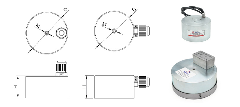
You can find the technical drawing and standard catalog dimensions of the product in the table below. Please contact us for custom size production.
|
MODEL (BYR5CK/ BUR5CK) |
Dimensions (mm) |
Power WATT |
Voltage VDC |
Duty Cycle % |
Connection POSITION |
Cable Gland PG7-9 |
Min. Plate Thick. (mm) |
Pull Force (N) |
||
|---|---|---|---|---|---|---|---|---|---|---|
| ØD | H | M | ||||||||
| Ø40x30 mm | 40 | 30 | M6 | 5.2 | 24 | 50 | TOP/SIDE | PG7 | 5 | 470 |
| Ø50x30 mm | 50 | 30 | M6 | 7 | 24 | 50 | TOP/SIDE | PG7 | 5 | 760 |
| Ø63x35 mm | 63 | 35 | M6 | 10 | 24 | 50 | TOP/SIDE | PG7 | 8 | 1000 |
| Ø80x40 mm | 80 | 40 | M8 | 15 | 24 | 50 | TOP/SIDE | PG7 | 10 | 2400 |
| Ø100x45 mm | 100 | 45 | M8 | 25 | 24 | 50 | TOP/SIDE | PG7 | 15 | 3400 |
| Ø150x55 mm | 150 | 55 | M16 | 37.2 | 48 | 50 | TOP/SIDE | PG7 | 25 | 9300 |
| Ø180x65 mm | 180 | 60 | M20 | 50 | 48 | 50 | TOP/SIDE | PG7 | 30 | 15000 |
| Ø200x60 mm | 200 | 60 | 3xM12 | 65 | 48 | 50 | TOP/SIDE | PG9 | 35 | 25000 |
| Ø250x80 mm | 250 | 80 | 3xM12 | 90 | 48 | 50 | TOP/SIDE | PG9 | 40 | 30000 |
| Ø280x110 mm | 280 | 110 | 3xM12 | 150 | 48 | 50 | TOP/SIDE | PG9 | 50 | 40000 |
| Ø300x130 mm | 300 | 130 | 3xM12 | 180 | 48 | 50 | TOP/SIDE | PG9 | 80 | 45000 |